Introduction
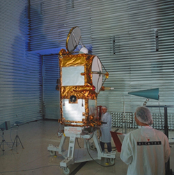
COROT experiment is embedded on the PROTEUS plateform. It a multi-mission plateform designed by CNES agency for instrument of 300 to 500 kg. with up to 250 kg payload and conceive to fly since 450 to 1500 km orbit
When the COROT experiment will be available it will be time to proceed to interfaces tests before the last step that is to connect the COROT instrument to the PROTEUS plateform. At this time we know that the official PROTEUS simulator will not be available for the meudon team.
Moreover some sub-system tests will require specific interfaces like CS16 type (Control Serial), AS16 type (Acquisition Serial), LLC type (Low Level Command), HLC type (High Level Command), DBLA type (Digital BiLevel Acquisition), DRA type (Digital Relay Acquisition) and MIL-1553 bus for DPU (Data Processing Unit) testing.
So we must design our own PROTEUS simulator and realize the required electrical and fonctional systems identical (almost) to the real platform.
A pre-study has been made for CS16 type link in 1999 by 3 students coming from the Cachan IUT : : Marc Balu, Cédric Bara and Sylvain Bergé.
The simulator
The hardware simulator is controlled throught an asynchronous 3-wire serial line (RX, TX and GND) at 115 KBauds. A LabVIEW application as well as a Borland C++ Builder application running under W2K OS controls the simulator. Regarding to the required real time constraint level it is possible to send TC to the target while monitoring the 8Hz clock through the serial line, or download a batch program that will run on the target and will run as a stand-alone system.
We can see here the Borland C++ Builder GUI :

In a first step the simulator is designed to drive a half instrument. For driving a full instrument it will be necessary to double the system and synchronized both system together (one master).
The simulator looks like a 3U 84E cabinet KM6-II series with :
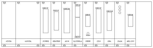
 |
|
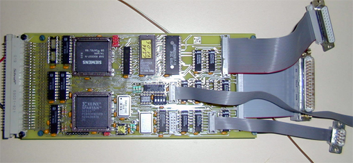
The PROTEUS-6 prototype with all connectors for AS16, LLC, DBLA and serial links. We can see on the left the backplane connector designed to extand the bench fonctions (DRA, CS16, synchro, ...) through a buffered processor bus. The 2 big components are a Siemens 80C537 microcontroller and a Xilinx SPARTAN XCS10 IC |
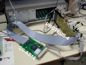
The sti-AS16 board
This board is used to debug the PROTEUS-6 board by generating answers to AS16 link request. It's a DPU simulator reduced to AS16 links.
 |
 |
|
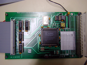
The sti-AS16 board, fitted with SBDL drivers DS26C31 and DS26C32 on the left and with the Xilinx SPARTAN FPGA containing the DPU emulator fonctions. |
The board in test configuration with PROTEUS board. |
The DPU simulator named "sti-AS16" (for AS16 stimulis) replies predefined 16 bits words simulating ecartometry infos on the dedicated AS16 line, synchronized to the clock and envelop lines generated by PROTEUS board. Corresponding schematic is here.
CK-PROT board
This board generates clock signals required by DPU and BS2 and includes DRA ( Digital Relay Acquisition). It is designed to drive DPU clock for acceptance phase (8Hz and 1/32S) and BS2 clock inputs for BS2 acceptance and integration.
CS16 board
Technical datas
We'll find here the PROTEUS release 4 schematics
Here lies a Xilinx FPGA implementation datasheet able to drive 8xDATA-CLK-ENV AS16 links simultaneously (designed with VHDL).
Les différents liens
"Commande Série 16 bits" : it's a TC SBDL standard (Standard Balance Link). The 16 bits word is serialy sent synchronous to a clock and an envelop.

"Acquisition Série 16 bits" : it's a TM SBDL standard (Standard Balance Link). The 16 bits word is serialy received synchronous to a clock and an envelop generated by the requierer
"Low Level Command" : it's a 26mS ± 2mS true pulse TC, SBDL standard. , used for 1/32Hz, or DPU reset signals
"High Level Command" : it's a 26mS ± 2mS true pulse TC, with a high level at 28V
"Digital Bi Level Acquisition" : it's a differential input SBDL standard
"Digital Relay Acquisition" : it's a single ended signal referenced to GND.
Régis Schmidt, COROT-ETC, March 2003